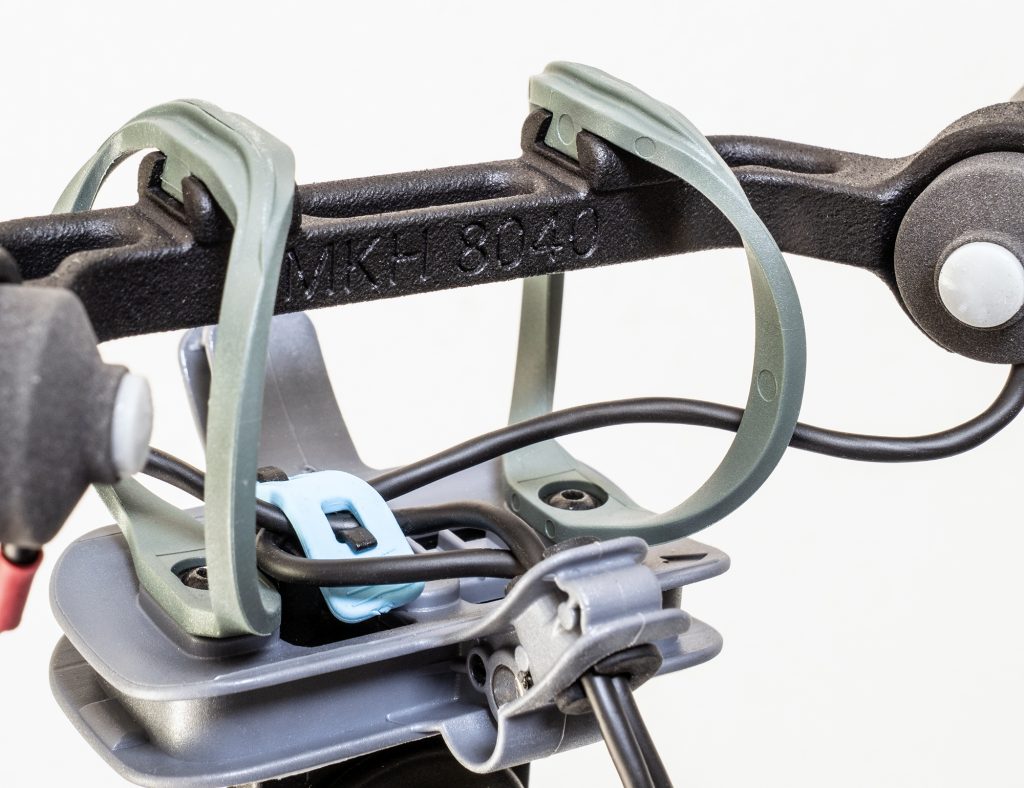
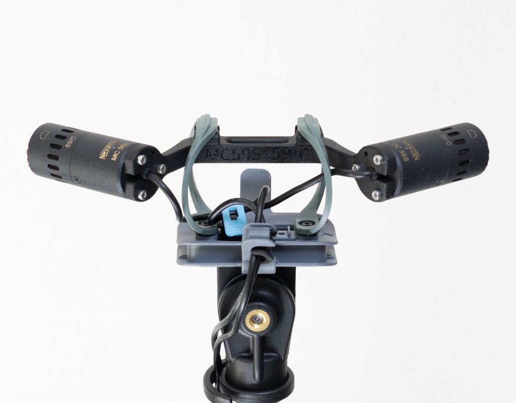
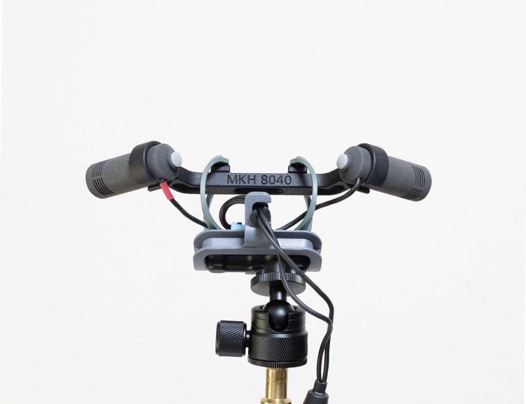
Close-up of the new Radius Mini-RAD hoops showing dovetail connection to a new MJF-printed ORTF bar for the Mini-ALTO (in this case for the MKH 8040).
Introduction
Last year I wrote a three-part series on fitting an ORTF pair in the diminutive 80mm diameter Mini-ALTO from Radius Windshields. This was, as I described, a (non-commercial) challenge from John and Simon at Radius, and I made the task a little trickier for myself by keeping the capsules of the mics on the centre-line of the windshield: too often people squeeze ORTF pairs into windshields with the capsules right against the basket, with consequent impact on wind protection. The result, as readers may recall, was a series of designs for some suitably short mics: the small cardioids I found that fitted properly were limited to the Schoeps CMC 1 KV + MK4, the DPA 4011 + MMP-GS or MMP-ES preamp, the Nevaton MC 59S + 59/C, and the Sennheiser MKH 8040. The first three are hard-wired and, crucially, avoid the projection of connectors, while the Sennheiser needs a custom MZL connector to become short enough to fit. Since then, I have added the new Nevaton MC59uS + C2 combination, which, with a length of 23.5mm, is unbelievably short for a cardioid mic.
In an update to part 3 of the original series on the ORTF in a Mini-ALTO project, I added that Radius Windshields had introduced an ORTF add-on kit with the necessary symmetrical pods (each 90mm) and fur to fit, and that Ed at ETK Cables was producing Y-cables with the customized MZLs necessary for the MKH 8040 version. I also posted links to (freely available) parts for 3d printing so that readers could make their own mounts, and I have had some feedback from those that have done this. Obviously, refinement of the mounts and turning them from homely 3d prints to injection-moulded parts would have been great, but, needless to say, ORTF in a Mini-ALTO is a tiny potential market for Radius Windshields – not least given that the necessary mics are, for the most part, relatively unusual: only the MKH 8040 is what one might call a ‘mainstream’ cardioid used in field recording and, indeed, it is this for which I have seen most interest (as gathered from feedback by those DIY-ing their mounts from my 3d files).
So the project could well have rested there, except for two things: first, I have been experimenting with getting Multi Jet Fusion (MJF) 3d prints made for me; and, second, the advent of the new Mini-RAD hoops got me thinking about revision of the ORTF in a Mini-ALTO design. This post, therefore, is about how those two aspects have come together and nudged the project on.
Detail showing the dovetail joint on the top of one of the MJF bars to fit the Mini-RAD hoops: the dimple mates with the pip on the underside of the Mini-RAD’s dovetail to ensure that nothing slips out. They are a tight fit anyway.
The revised design
The attraction of MJF printing for me, vs my modest 3d printing at home, has been that it liberates the designs from a flat bed. I know that people use supports, that are then removed, in their prints, but I have had little joy with this and invariably end up with a pile of spaghetti. So, getting one-piece prints of complex pieces instead of having to make them up piecemeal, with brass inserts and screws holding them together, seemed a real advantage: in short, for much I am doing nowadays I am using the little printer I have here (a Bambu Lab A1 Mini) to test things, then get them printed commercially using MJF technology.
I had just begun refining the ORTF bar designs for MJF printing – essentially combining the mic clips/mounts with the bar that holds the mics at the right angle and spacings, when I realized that the pre-production Mini-RAD hoops from Radius were imminent and that by using these I could simplify the designs. All the mounts for the ORTF pairs for the Mini-ALTOs had a common feature in that two posts or connectors linking the ORTF bar to the top of the hoops, so that the bar and the mics sat centrally in the windshield. With the much smaller Mini-RAD hoops (they are c.19mm shorter internally) it was clear that the posts/connectors could be removed from the design, and, instead, the ORTF bar could be fixed directly to the hoops. Also, the Mini-RAD hoops do not have a screw fitting at the top, as found in the standard hoops, but, rather, use a dovetail joint to connect: the dovetail includes a pip, which fits into a dimple in the Radius clips to ensure that the two parts don’t slip.
OK, a picture is worth a thousand words, so here are a few that, I hope, clarify how the new designs work and compare to the previous approach. In these examples, the updated designs are for the two Nevaton variations and for the Sennheiser MKH 8040, for the simple reason that I own these mics: I had to borrow the Schoeps and DPA short cardioids for the designs and tests last year.
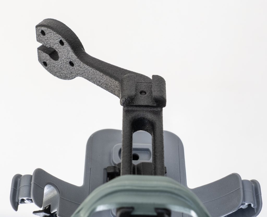
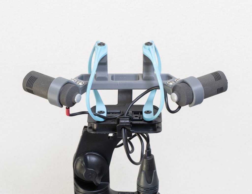
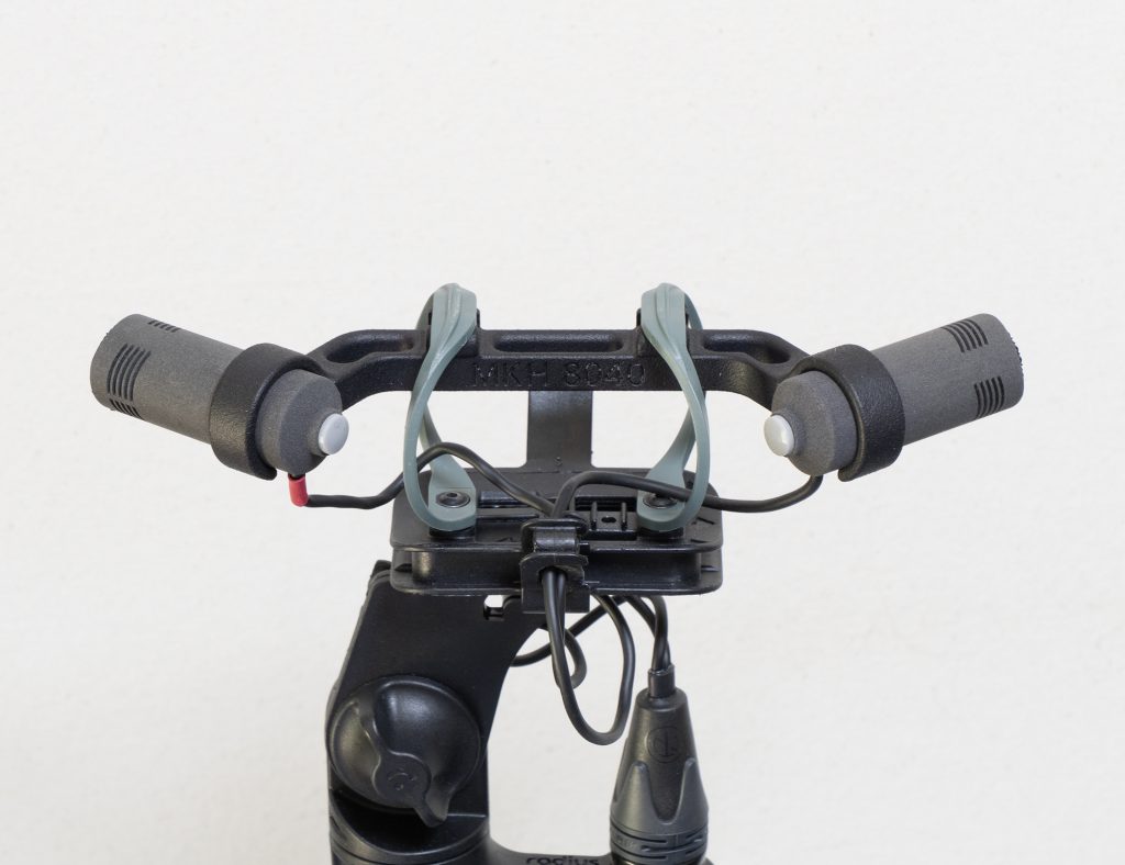
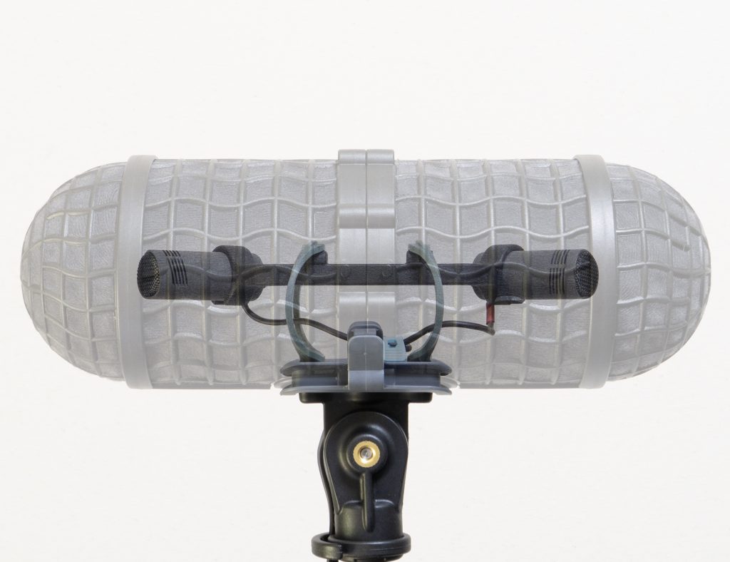
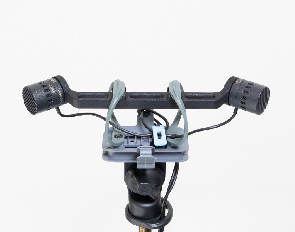
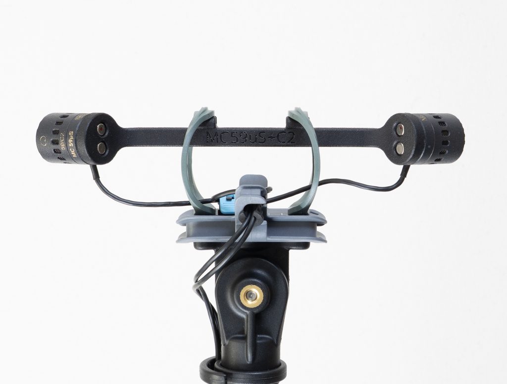
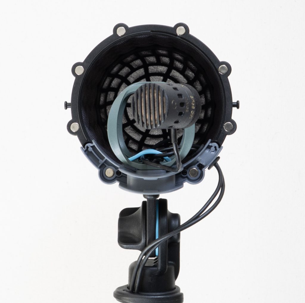
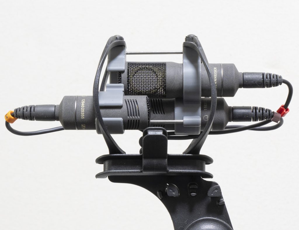
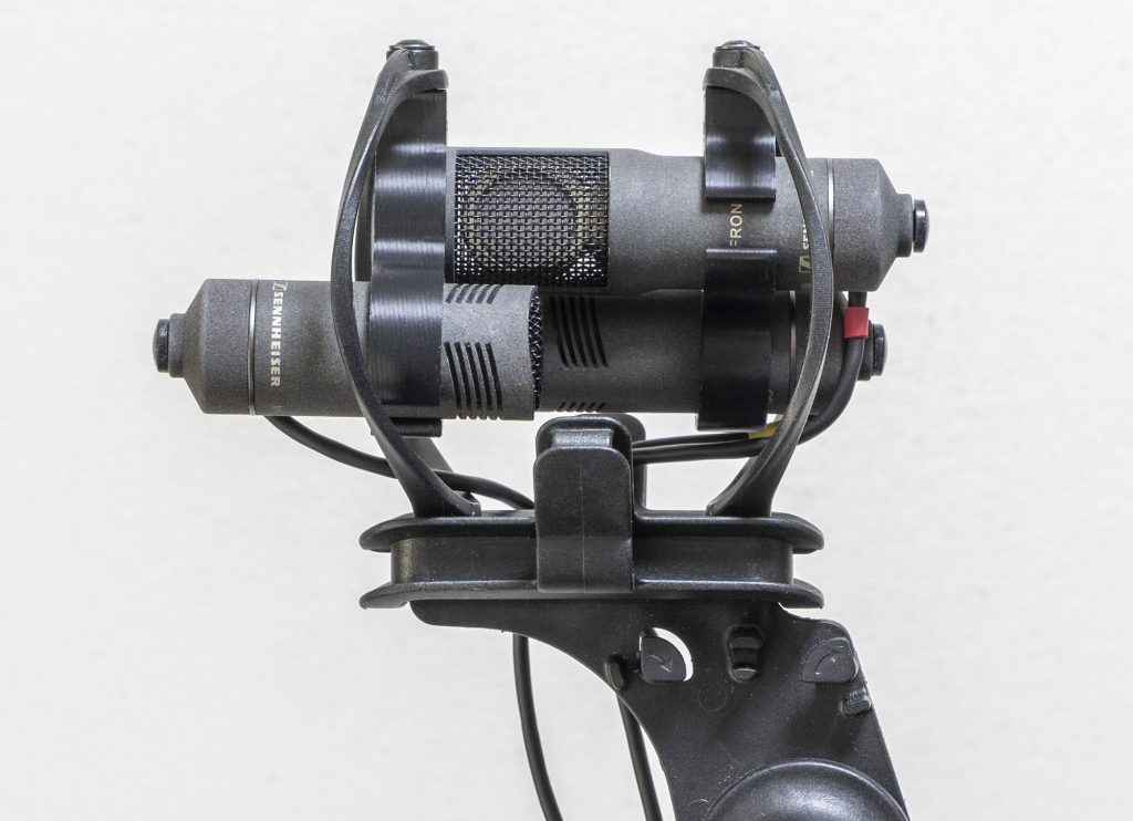
Here – as a recap – is the previous design with the standard RAD-2 hoops, showing the posts that connect the hoops to the ORTF bar and the separate clips for the mics themselves (in this case, MKH 8040): so a five-part assembly.And here is the revised design, with the one-piece MJF printed ORTF bar with integrated clips and no posts necessary to connect to the hoops. Again the mics are MKH 8040.Close-up of the new ORTF bar for the MKH 8040 showing the small groove inside the mic clips that ensures correct positioning of the mics (there is a slight projection where MZL meets the body of the mic).Composite image showing the ORTF bar with Mini-RAD hoops within the Mini-ALTO ORTF edition (i.e. with two 90mm pods), showing how the bar and the mics sit centrally in terms of height within the windshield.A single-piece MJF ORTF bar with the new Mini-RAD hoops, with the very short Nevaton MC59uS + C2 combination.Rear view of the bar for the Nevaton MC59uS + C2, showing the magnetic mounting of the mics.Side view of the Nevaton MC59uS + C2 ORTF pair, showing that the capsules remain central to the windshield basket: essential to maximize wind reduction.Mini-RAD ORTF bar for the Nevaton MC59S + 59/C combination: the preamps in this case are attached to the bar with M2 screws.
Conclusions
So there we go. From tests, there is no difference in performance and, indeed, you wouldn’t expect there to be, as long as the right compliance hoops are used (and the smaller hoops need a softer Hytrel to match the compliance of the larger hoops: for example, 45D shore in the Mini-RAD is roughly equal to 55D shore in the standard hoops; 55D = 62D etc.). But the new designs are useful simplifications of the previous versions, a lot further on from proof-of-concept designs, and as near as possible to the slick and robust injection-moulded versions that would be the ultimate, but which I think are not commercially viable. I hope this postscript to the original series on the ORTF in a Mini-ALTO project inspires others to venture along the route of bespoke shockmounts. And let it serve as a warning: the Mini-RAD hoops will doubtless feature in more elaborate and esoteric shockmount designs here!
Update: 22.7.2026
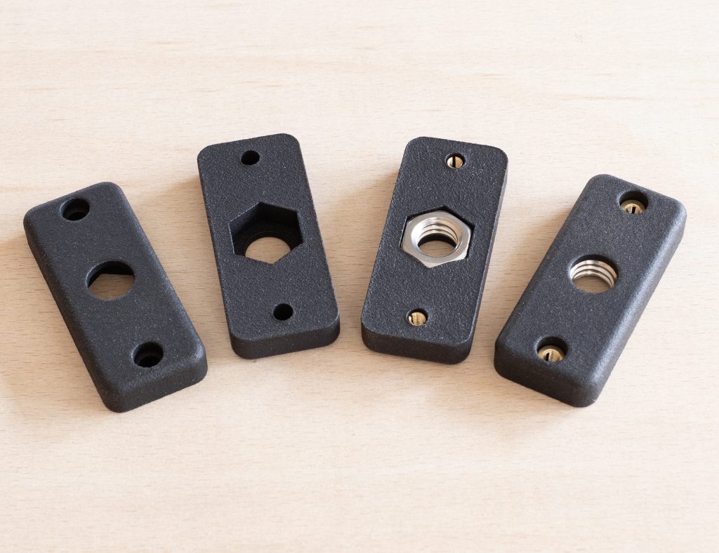
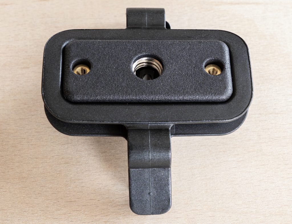
A postscript to a postscript? Hmm. Anyway, just thought I should add a short piece on base adapters. Obviously, the pivoting bases for RAD-2 and Mini-ALTO connections to boom poles, stands etc. pivot up and down the way expected for a mono mic or, indeed, an MS pair, but not for an ORTF pair where the windshields is used side-on to the sound source. In my original development of a 3d-printed solution I came up with a very simple base that allowed a 3/8″ connection to a ball head, and I have very slightly tweaked that basic design for MJF printing, retaining the captive 3/8″ UNC nut (a nice tight fit into the MJF base) and M3 brass inserts:
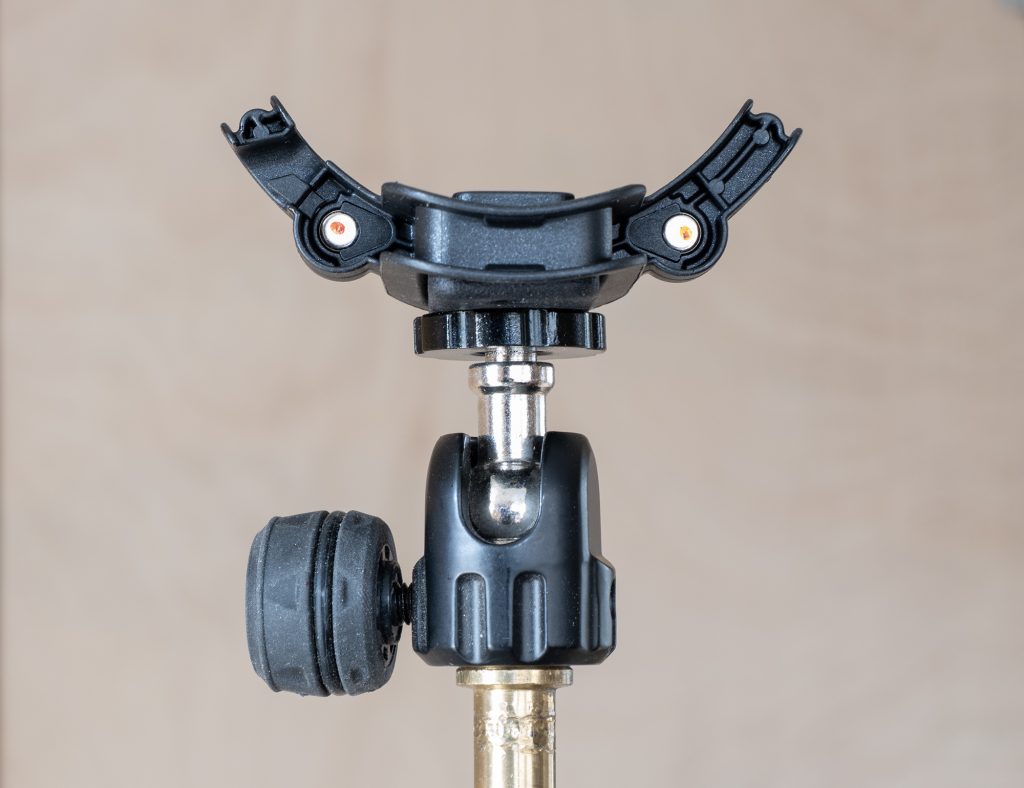
Simple base adapter in MJF with and without the 3/8″ UNC stainless-steel nut and M3 brass inserts.Simple base adapter in MJF inserted in the bottom of the ‘smiley face’ of the Mini-ALTO.Simple base adapter in MJF inserted in the bottom of the ‘smiley face’ of the Mini-ALTO, with a 3/8″ ball-joint attached (in this case the Gravity MSQT1B).
In due course I am sure Radius will produce something rather better and, indeed, their upcoming 1/4″ adapter bar is not at all bad and, with it’s 1/4″ female thread, allows use of some well-machined small ball joints that are rather nicer than the 3/8″ one from Gravity pictured above.
ORTF pair with upcoming Radius Windshields 1/4″ adapter bar – printed in MJF prior to the injection-moulded version being made – connecting the ‘smiley face’ to the ball joint (in this case one branded ‘Innorel’, but seemingly sold under several names: but nicely made nonetheless).
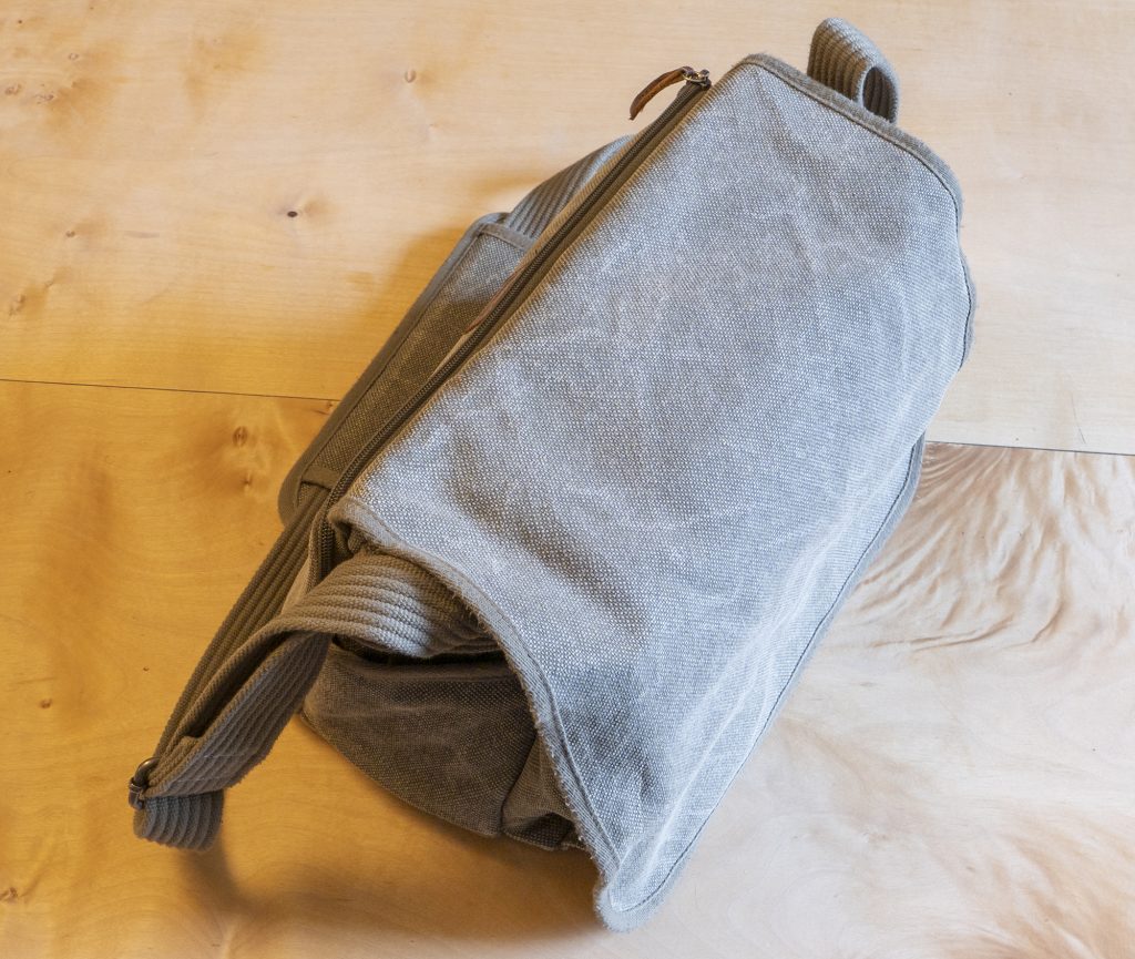
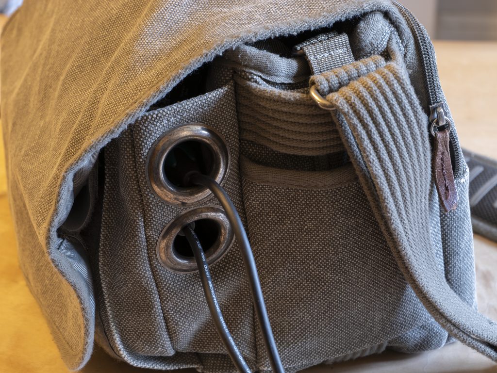
My Think Tank Retrospective 7 (old style) before butchery. Tough as old boots, compact, hold all the bits and bobs I need, and doesn’t yell ‘expensive sound recording kit’.
Bags for audio location recording are made a plenty, for all sorts of sizes of mixer/recorders and ancillary gear. But they have one thing in common: they are all geared for production sound or similar use. I’ve had several over the years, and just have one nowadays for a Sound Devices 788T paired with an CL-8. It’s fine for when I am recording or mixing sound for film/video, but I’ve never got on with such bags for field-recording. For that I’ve found the needs are quite different as, if not hiking and requiring a backpack (and for that I use a Vango Trail 35 or a North Face Borealis), I want a shoulder bag that has several attributes missing from a sound bag: it needs to be discreet, and must have capacity for additional things such as pens, notebooks, cables, a camera, mics and a windshield. Even a bottle of water. More to the point it must be able to carry those things – especially little items – securely: sound bags are so permeable that even if you can fit additional items in them, there is a high risk of them slipping out, which ain’t too good if you are knee-high in nettles, squatting in the salt marsh, or strolling down the Kilburn High Road. Equally, a production sound bag has things I simply don’t need in the field: I don’t need a raft of pockets for wireless receivers; I don’t need a clear plastic lid to allow me to ride the faders for a live mix while standing in the rain; and I don’t need to be able to connect a harness. I’ve seen many persisting with audio bags in the field and have no idea why so many do: being charitable, perhaps they find them perfect in a way that I simply don’t; or, being less charitable, perhaps they think a sound bag must be the right tool even if there’s no boom pole or actor in sight, and just suffer the inconvenience? I suspect a mix of the two. And, of course, while a production sound bag might be the right tool for one day’s field recording, it might be the wrong too for the next day’s session, even in the hands of the same recordist.
Anyway, I can only speak for myself (evidently!) and I’ve long used other bags for most field recording projects. The ones I have used – initially bought for cameras – for many years have been the rather lovely thick canvas Think Tank Retrospective bags. Of these, my favourite for field recording is my smallest one: the Retrospective 7. It’s smaller than my production sound bag, yet is so more space efficient. In short it’s my perfect small rig field-recording bag apart from one slight niggle: it’s a little fiddly routing mic cables from the sides of the mixer/recorder since, of course, the bag lacks the side exits for cables that I have just lambasted in production sound bags. OK I could have low-profile XLR jumpers, but that rather goes against the streamlined minimalism in the field. At the back of my mind for years has been the thought that one day I would find some massive eyelets to make a few neat holes that would help with cables, but which wouldn’t throw out the baby with the bathwater and lose the fact that the bag could hold things safely like…well, like a bag should!
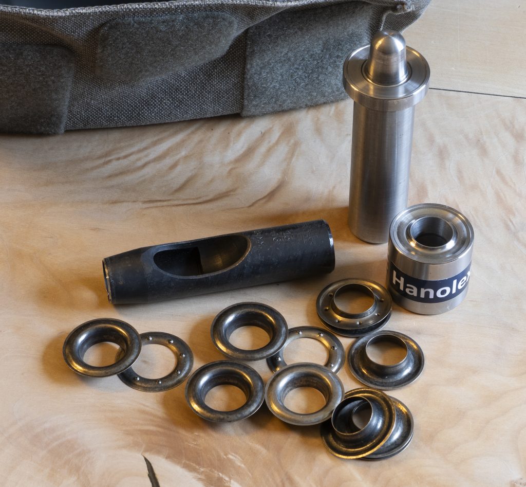
This weekend, I finally got around to it. A little bit of research had showed that what I needed to comfortably fit an XLR plug and, say, another cable through a hole would be 25mm (internal diameter) curtain eyelets. I ended up on the website of specialists Hanolex, in Rochdale, and goodness gracious they were fantastic on the phone when I asked the gormless question: what is the difference between a curtain eyelet and other eyelets (the answer: nothing really, just size and the availability of different finishes). Within a couple of days I had the tools and eyelets (their antique nickel ones were a great match) in hand and set-to, destroying my lovely bag…
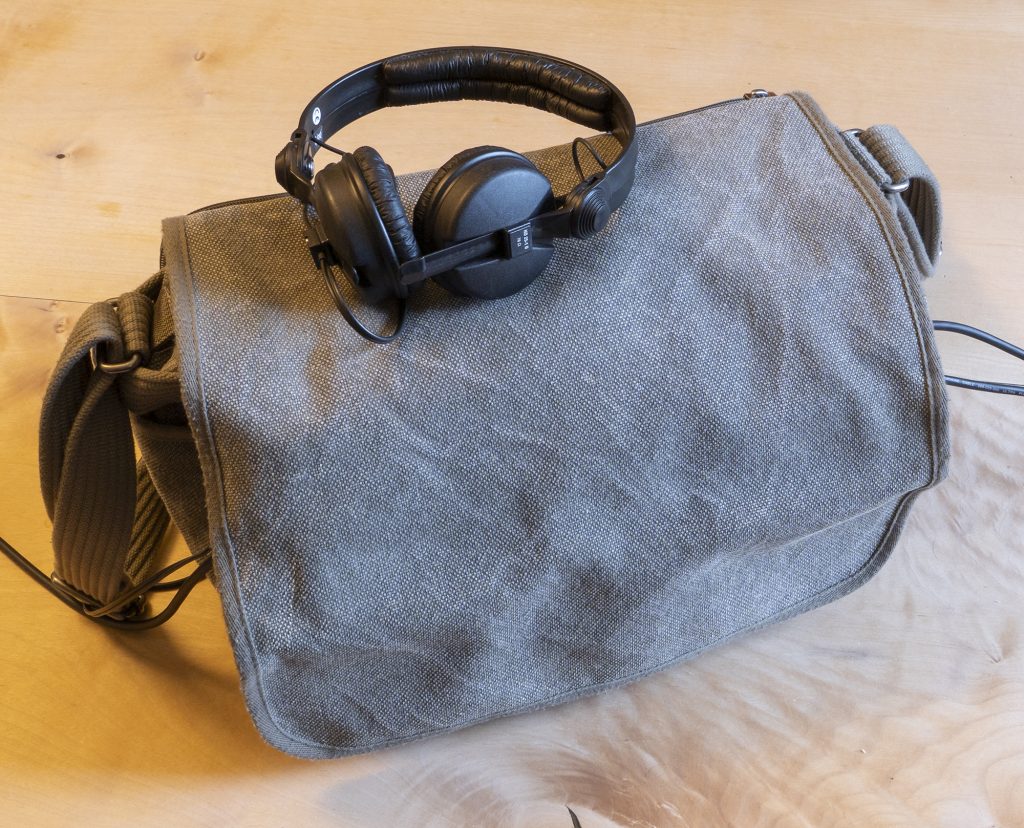
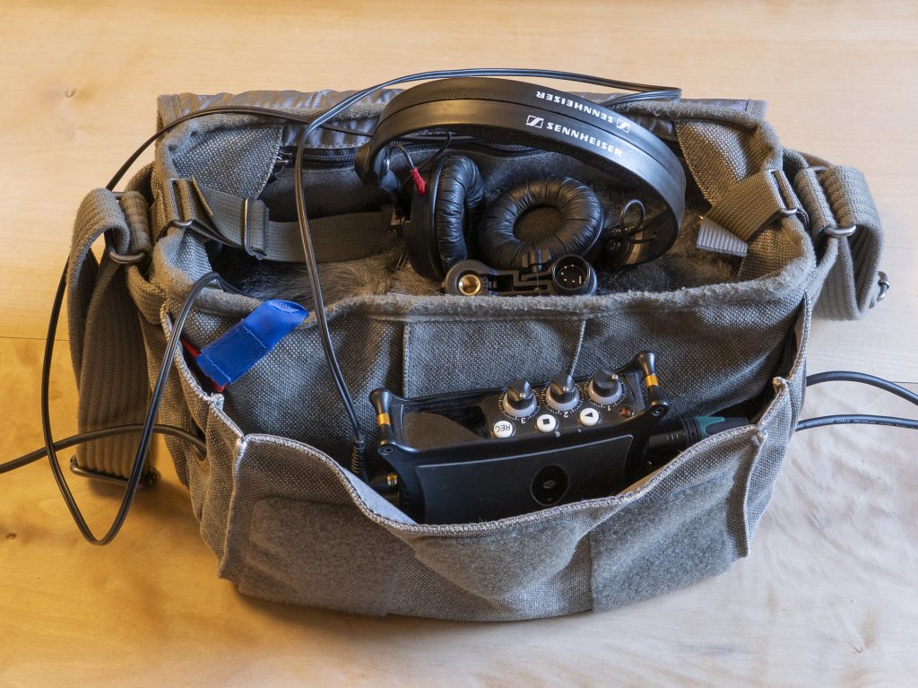
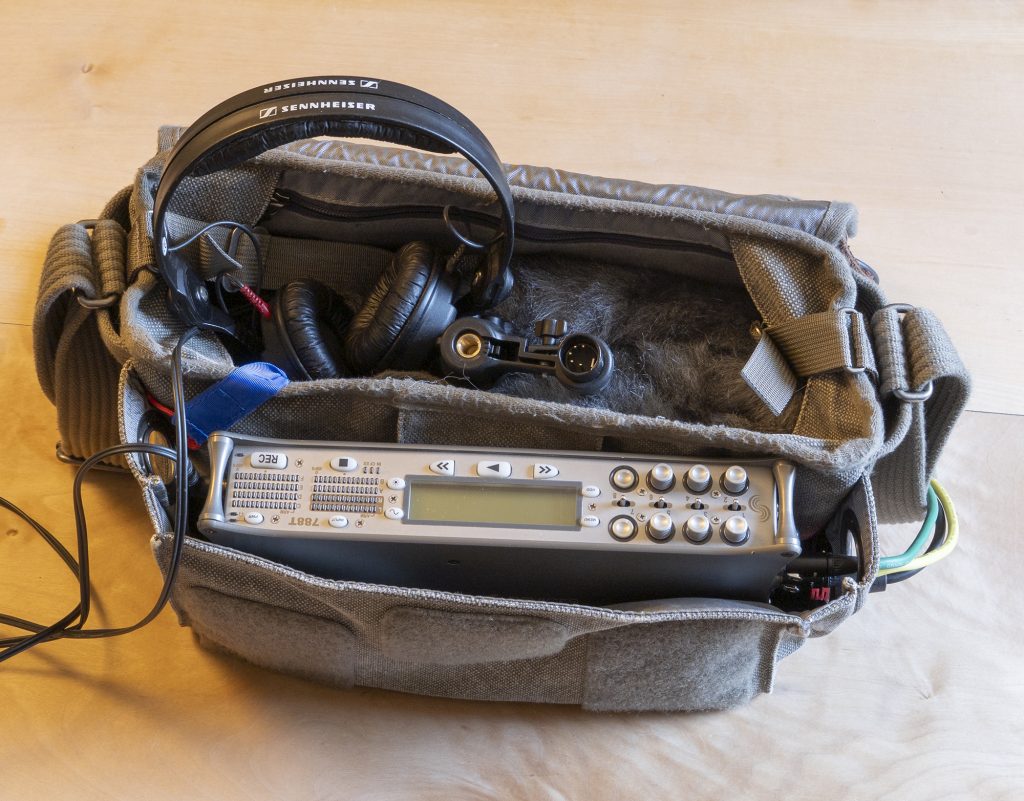
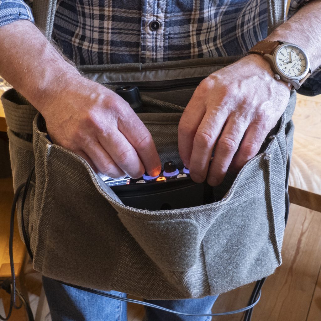
The tools for the job, and some antique nickel eyelets that are a pretty good match for the metalwork on the bag.Oooh: cables now coming out the sides, like a production sound bag…I just went for a couple of eyelets in each side of the front pocket (one of three main pockets), keeping them high enough up so that small things won’t slide out, not that I have many such things in the same pocket as the recorder.It’s a small bag, and I often use it with my little MixPre-3. But as filled here it also has a camera (micro four-thirds) and – you can just about see this – a Mini-ALTO 250 windshield (with an MKH 8018 in it), as well as usual spare batteries, headphones, other cables, and many little items.But, hey, if I fancy it, I can even stick a 788T in the bag.Now it may not be quite as ergonomic as my production sound bag for actual mixing, but it’s perfectly accessible for setting gain etc. and, I don’t know about you, but I don’t ride the faders to mix live to the LR mix tracks for field recording!
Now, it is entirely reasonable to wonder why on earth would anyone write a blog post about making four holes in what was a perfectly nice bag beforehand? On one level it is as silly as posting a photo of a meal you are meant to be eating or, worse for others, a live gig you are meant to be enjoying (yes, I can be a stereotypically grumpy middle-aged bloke), but there may be someone out there who is unthinkingly struggling with a production sound bag, perhaps attracting unwanted attention when not actually recording, and losing items in the long grass. And there may be someone out there who has never come across the Retrospective bags or some other equally useful equivalent, or, if they have, hasn’t got to grips with whatever little niggle that stops it being the perfect field-recording bag for them. If so, this blog post is for you: get hold of an eyelet punch or whatever tool you need, and get butchering your bag. Just don’t blame me when it all goes wrong. And if you find production sound bags perfect for all field recording uses, then that’s fine, of course, though I suspect you won’t have reached the end of this post!
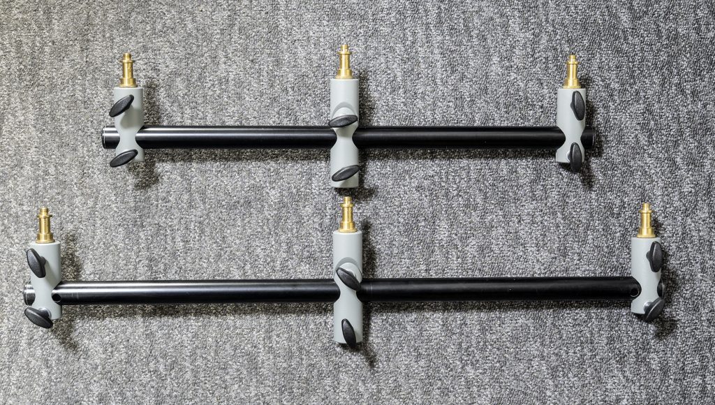
This might be one of my shortest blog posts ever, but that’s doubtless a refreshing change from some of my very long ones, especially if you read them on your phone! Anyway, I was just putting together the gear for a recording tomorrow morning and while grabbing a stereo bar, I thought it perhaps worth highlighting, first, how over the years I have found the Manfrotto 154b to be a great option and, second, how easy it is to modify.
Like many others, I have found the 154b to be an eminently affordable stereo bar, a decent length (spigot centres up to 620mm), really adaptable, quick to set up and adjust, keeps the mics as set, strong, and robust. And if you have a few, like I do, you can add more of the connection clamps that hold each mic when you want, say, four mics on the bar: and it is much cheaper doing that than ordering additional clamps (part R154,01). But, over the years I have noticed that some dismiss it, especially for field recording, for two features: it has an aluminium tube construction that can resonate (not often an issue) and it has two holes near the ends that, if the movable spigots are not over them, can catch the wind when used outdoors. For many uses I deploy the 154b as sold with no issue, but often I don’t want such a long bar so I have a modified version that is 520mm long: this fits neatly in a rucksack I often use when field recording, and is no longer than the (folded) tripods and stands I pack with it. Obviously cutting an aluminium tube to length is no great deal and needs no special gear (care and a junior hacksaw would suffice if you don’t have much of a workshop) and, as long as you cut both ends off, then the two offending holes will be removed. The plastic end caps can then be knocked out easily from inside, so no need to scuff them by prising them off. And, finally, you can do as I did and stuff the inside to damp any resonance: I just used a bit of Rockwool insulation I had spare, but I am sure anything similar would do the trick. So, 10 mins work and, voila, a slightly more compact stereo bar fit for anything in the wilds.
All very obvious, I know, but it might just help someone view the 154b a bit differently!
Like many, I have used double mid-side (DMS) from time to time and, doubtless less typically, I have used horizontal native B-format arrays too: I have written a couple of blog posts on the latter already. Given that DMS can be converted to horizontal B-format and vice versa, I have wondered why DMS is much more widely used and, more specifically, about the practicalities of mounting both arrays: in short, are the two advantages of DMS in use that a) it requires one fig 8 mic only (vs the two for native B-format) and b) that it lends itself better to compact mounting that fits more easily in a windshield? And if DMS is often achieved using this compact mounting – with the three horizontal mics clustered together – would it be better if implemented more spaciously, and with less difficulty in terms of mounting the rearward-facing cardioid, along the lines of a horizontal B-format array?
Now, fear not, this isn’t a blog post about the theoretical side of DMS (or, indeed, native/horizontal B-format) nor, for that matter, about why anyone should use it in preference to affordable ambisonic mic options (and there are compelling reasons): for that, you are much better in the care of Dr Helmut Wittke (CEO of Schoeps) and his colleagues in publications such as this: Wittek, H., Haut, C., and Keinath, D., Double M/S – a Surround recording technique put to test (Schoeps paper, 10.03.2010).
Rather, this post is about some of my dabbling with practical implementations of DMS rigs both generally and in the context – or constraints – of windshields, and with reference to the analogous horizontal B-format rigs. I include some examples of commercially available DMS mounts (past and present) along with some of my own solutions. I hope it isn’t too much of an idiosyncratic ramble, and that it may chime with or, even, be useful for others.
NB having drafted much this blog post I found it rather long and, also, dividing into a few key sections, so I have divided into three separate blog-posts. This one, (part one), is concerned purely with the rigging options: my take on the options for how to mount mics for DMS. It is concerned with SDC mics and, also, doesn’t go into DMS with shotgun mics: it is primarily focused on rigs suitable for taking into the field (i.e. in windshields). Part 2 concerns practical comparison of the different rigs, not least exploring the reality of shadowing effects caused by mics sitting close to other mics. Part 3, to follow very soon, explores the practical differences between DMS and horizontal B-format set ups: there is so much in common – and conversion from one to the other is simple mathematically – but what are the practical pros and cons? Parts 2 and 3 include sound samples that you can download and play with.
Different mic mounting options for DMS
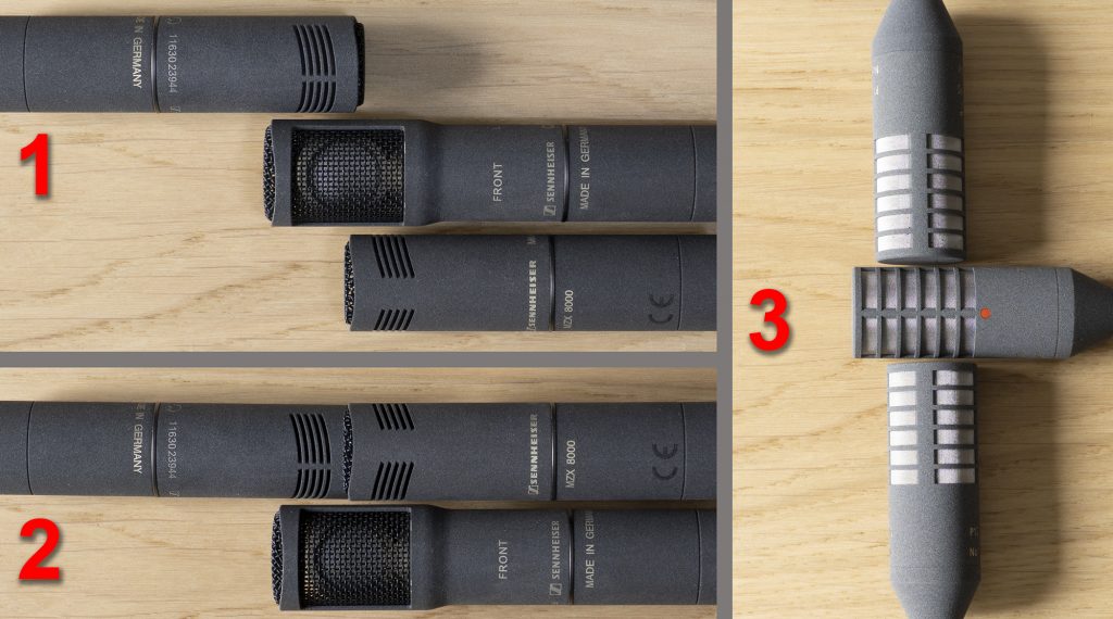
When using small-diaphragm condensers (SDCs) there are three main ways you can configure the three mics needed for DMS:
1) end-address mid mics combined with a side-address fig 8, so that all three horizontally-oriented mics are aligned vertically (typically the central mic is the fig 8, but not always so);
2) end-address mid mics combined with a side-address fig 8, so that all three horizontally-oriented are clustered more closely than in option 1, forming a tightly spaced triangle, but with the two mid mics horizontally offset from the centre of the array (the fig 8 can be above or below the mid mics); and
3) side-address mid mics oriented vertically, flanking, from above and below a horizontally-oriented fig 8.
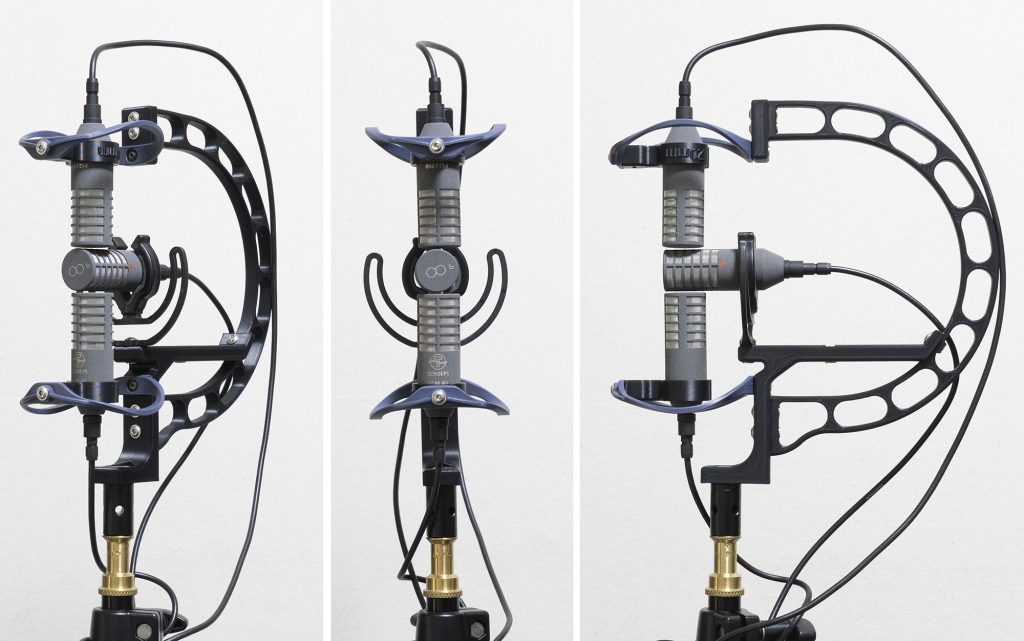
These three configurations are shown with unmounted mics in the image below:
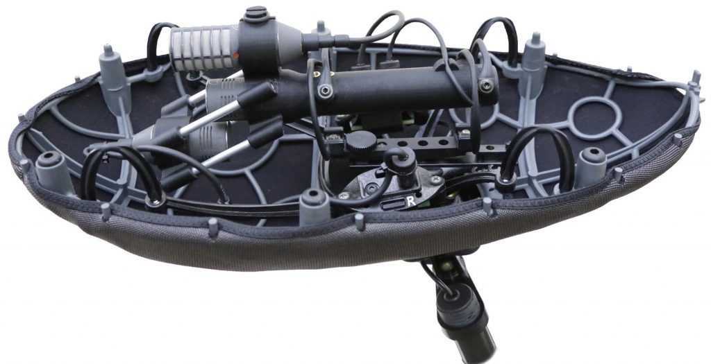
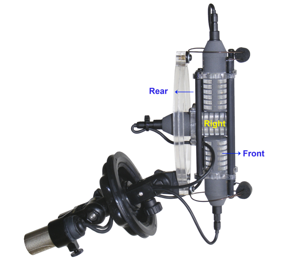
The three fundamental mic configurations for DMS, for clarity shown here without the complexity of mic support. In all three photos the view is as if from the side of the array and front is to the left.
The composite image above shows that, with the end-address mics (options 1 and 2), the forward-facing mic and fig 8 are easy to mount in the manner of a simple mid-side pair, with the complexity coming from the addition of a rearward-facing cardioid, the body of which projects awkwardly away from the front of the other two mics. In a studio context this can be supported by a separate mount and stand, but this still requires fiddly alignment and is a real pain when adjusting the location of the array to the best position. Obviously, mounting the three mics together is more practical and, indeed, is essential for use in the field in a windshield.
Option 1– end-address cardioids, all aligned
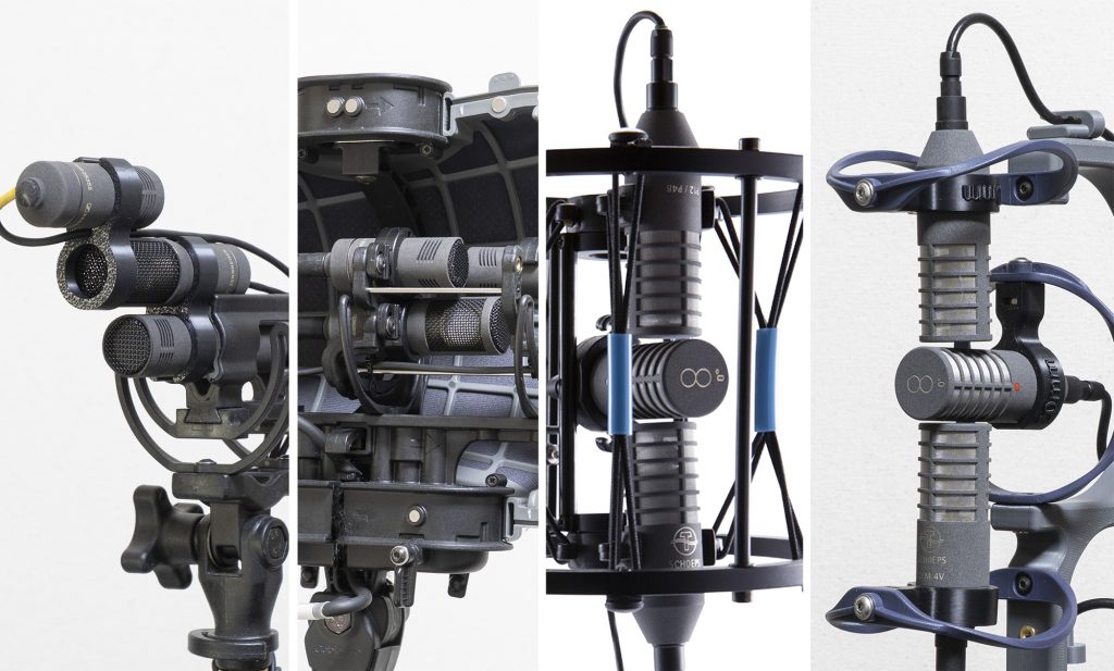
This option with the three mics aligned vertically, is perhaps harder to rig, but with shorter mics (such as Sennheiser MKH 8000 mics with MZLs, and Schoeps CCM mics) it is more feasible. Cinela, for one, has effective windshield mounting solutions shown below, where in each example the rearward-facing mic is supported by pairs of thin struts to reduce acoustic impact. In both these designs the central mic has a long plastic holder to extend the mic to the quite widely-spaced OSIX isolators, necessary to counteract the mass of the three mics at the front.
Cinela Pianissimo with DMS rig, with the mics (Sennheiser MKH 8030 + 2 x MKH 8040) aligned vertically: photo courtesy of Cinela.In this variation from Cinela, for Schoeps mics, the three mics are again aligned vertically, but the fig 8 mic (CCM8) is at the top: photo courtesy of Cinela.
Of course, where DMS rigs involve a shotgun for the forward mic, then the fig 8 and the rearward facing cardioid can be clipped above and below the long body of the shotgun: this is a not entirely satisfactory use of DMS given the polar pattern of a shotgun mic and the irregular response off-axis arising from its interference tube. With a little bit of head scratching and some 3d printing, similar options can DIY’d, although any shock-mount needs to be able to counter the front-heavy loading.
My 3d-printed DMS rig with the MKH 8030 and 8040 mics aligned vertically and in a Rycote InVision shock-mount. The mics are fairly unimpeded (even the cable – from ETK Cables with custom MZLs – for the top cardioid is routed through the clip and along the null of the fig 8), but, obviously, the rig is rather front-heavy and too tall for most windshields.
Option 2– end-address cardioids, side-by-side
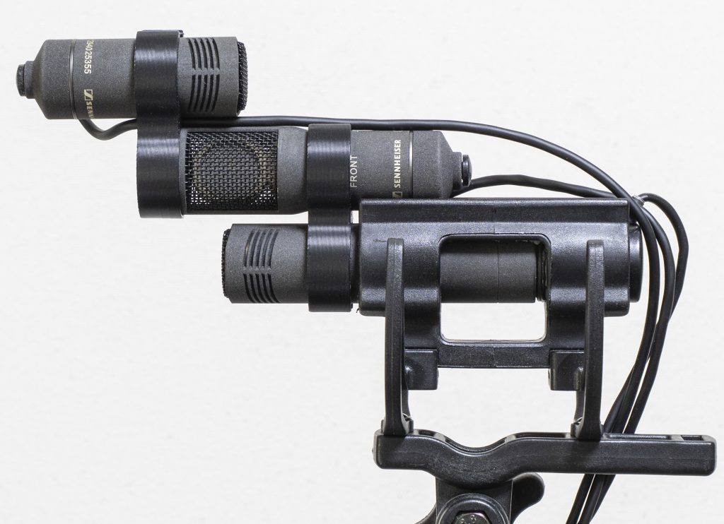
This mounting option, where the two end-address cardioid mics are positioned side-by-side, has become a common approach. As with the vertical configuration (above), mic length can quickly make things unwieldy: even the modest 78mm length of the Rycote CA-08 cardioid, plus a low-profile XLR connector, makes for a rather long projection of the front (rear-facing) mic, as shown here:
DMS with Rycote mics, showing the significant forward projection of the rear-facing cardioid despite its fairly short (78mm length).
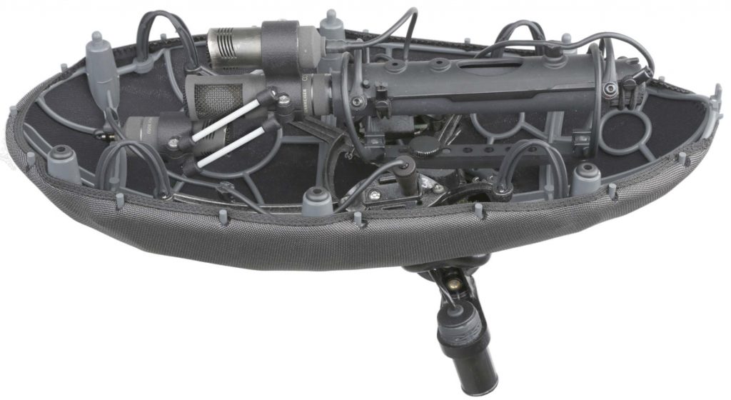
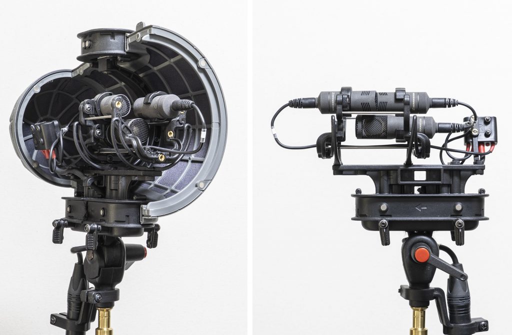
The more diminutive Sennheiser MKH 8000 mics with MZL connectors instead of XLR modules are, of course, the intended mics for my Rycote Cyclone DMS Kit 1, and show rather better the more compact end-result of the side-by-side cardioids in this option :
The Rycote Cyclone DMS Kit 1 with half of the basket shell in place, and with the basket and supporting arm fully removed. MKH 8030 and 8040 mics.
The constraints of the hoop size (which precludes vertical alignment) meant I also adopted this approach with my DMS mount for MKH 8000 mics in the diminutive Radius Windshields Mini-ALTO 115. As with the Rycote Cyclone DMS Kit 1, this uses thin stainless-steel bars to keep the clips aligned, but also uses the small front ring of the MKH 8030 fig 8 as a fixing point for a clip: it is workable if you need an extremely compact DMS array in a windshield, but is a bit fiddly to set up. Moreover, unlike MS pairs in the Mini-ALTO, DMS rigs in this windshield – or at least my attempts! – end up with the fig 8 mic between the hoops, so that the sideward-facing lobes of the mic are aimed directly at the rather chunky plastic ring where the two windshield pods join: obviously not ideal.
Another rig with DMS using the compact side-by-side cardioid approach: in this case my initial 3d-printed design for the Radius Mini-ALTO. MKH 8030 and 8040 mics, with a triple MZL cable by ETK Cables.A more recent – simplified – variant of the above, which is much easier to use (no fiddly rods). Again, MKH 8030 and 8040 mics, with a triple (customized) MZL cable by ETK Cables. The Onshape files can be accessed here for the front and the rear clips.
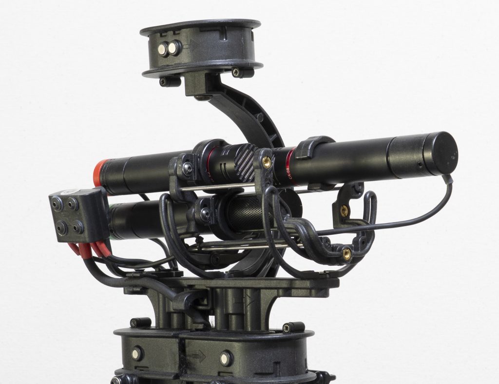
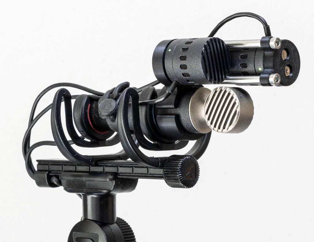
While this configuration for DMS is arguably easier to mount and is certainly more compact, there are two obvious downsides. First, the coincidence of the mics in the horizontal plane is lost, with both cardioid mics horizontally offset from the centre of the array. Given how much care is usually taken with MS rigs to ensure that the capsules of the two mics are aligned vertically, to ensure coincident time of arrival (and phase coherence) of sounds from the (usually predominant) horizontal plane at the two mics, this might seem problematic for higher frequencies (depending on spacing, but typically above c.10kHz). Such concerns are often over emphasized by the theorecticians, however, and in practical use – even recording, say, classical music – the effects of even side-by-side MS pairs are not always evident: one to bear in mind and check for your usage and ears, perhaps. The second downside, is that the mics are more obviously shadowing each other than when positioned exactly vertically above each other. The physics are undeniable, but, again, whether it matters or not will come down to how critical the recording is and the nature of the sound source. I will explore this – with sound samples – in Part 2 of my DMS blog-post series. And, of course, mic size comes into play: for example an MKH 30 + 2 x MKH 40 MS rig is quite a different beast to the MKH 8030 + 2 x MKH 8040 rig, especially if the latter uses MZL connectors as in the photos above. And you can take the miniaturization of the cardioid further: below is a photo of my Nevaton DMS rig using their new diminutive MC59uS/C2 cardioid mic, which is only 23.5mm long, with their MC59/8 fig 8. In this case the mics are too wide (22mm diameter) to fit in a Radius hoops (and are here shown on a Rycote Nanoshield shock-mount, although would work in any Rycote or similar windshield), but the difference in size between the fig 8, with its XLR connection, and the tiny cardioids makes mounting a bit easier and, of course, any shadowing effect is reduced to some extent by the shortness of the cardioids. On the downside, the MC59/8 has no front part to be used for support as in my MKH 8030-based DMS rigs above.
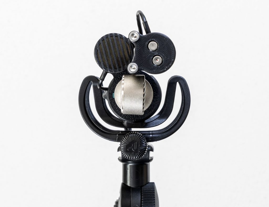
DMS rig with MC59uS/C2 cardioid mics and MC59/8 fig 8, using a Rycote Nanoshield shock-mount. This is a fairly clean (in the sense of minimizing shadowing from mics and mount parts) version of the side-by-side cardioid option, although the ‘lollipop’ design of the fig 8 means supporting that rear-facing cardioid out front is a tad trickier. Now if someone would make a fig 8 mic with fixings on the front/top (say a couple of M3 threaded holes) that would make life so much easier for DMS rigging!DMS rig with MC59uS/C2 cardioid mics and MC59/8 fig 8: head-on view. The cardioids use magnetic mounts.
Option 3 – using side-address cardioids
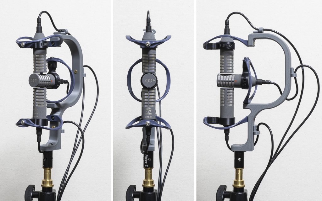
This mounting option, using side-address cardioids, used to have two commercially-produced options in the form of the Cinela Z-DMS-CCM (for the Cinela Zephyx, launched in 2005) and the Schoeps/Rycote WSR DMS LU (introduced by 2005), which were both designed for the Schoeps CCM8 + two CCM4V combination. The Schoeps/Rycote mount is certainly discontinued, although I understand that the Cinela mount, although no longer on their website, is still produced occasionally as a special item: make certain you ask nicely! The Schoeps option was used to illustrate Wittek et al’s paper on DMS and appears to have been Schoeps’s preferred implementation of DMS for some time, but currently the DMS options on their website use end-address mid mics either in Rycote Cyclone or Cinela Pianissomo windshields. The Schoeps/Rycote and Cinela methods of rigging the DMS setups with side-address cardioids are quite different as you can see from the photos below:
Schoeps/Rycote WSR DMS LU, with Schoeps CCM8 + two CCM4V: photo courtesy of Schoeps.Cinela Z-DMS-CCM shock-mount for the Cinela Zephyx, again for the Schoeps CCM8 + two CCM4V combination: photo courtesy of Cinela.
I came across both these mounts for DMS with the side-address Schoeps CCM4V only more recently when wondering if my thoughts on adapting the approach taken for horizontal B-format rig to DMS had any precedents: evidently, there is nothing new under the sun! Of course, both the Cinela and Schoeps/Rycote mounts could be used for horizontal B-format too, but I have no idea if that has ever been done: you would hope so.
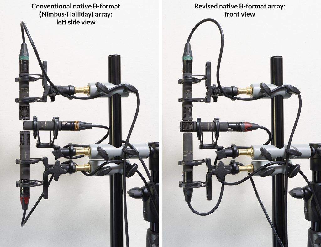
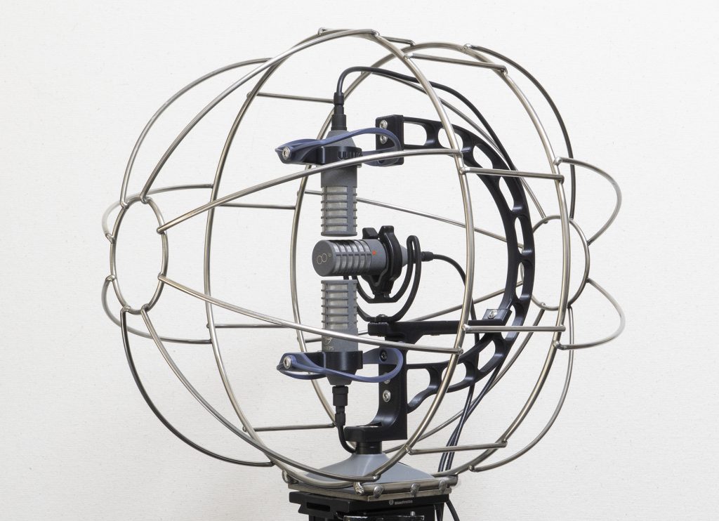
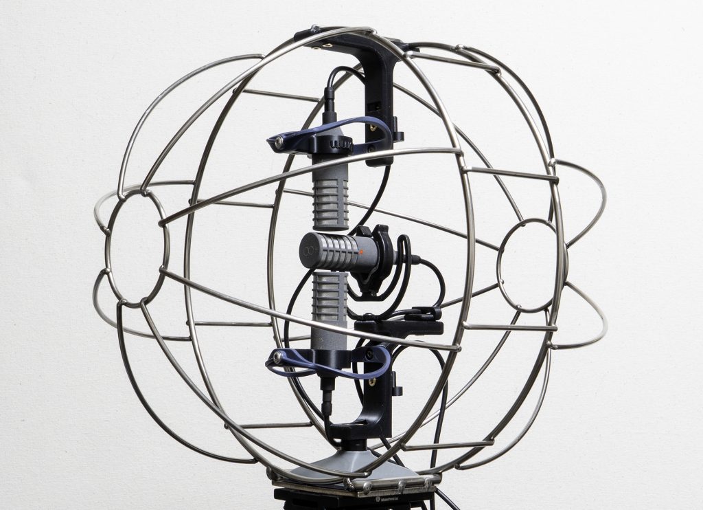
The two different configurations of horizontal B-format figs I have been using (the revised version having the omni mic rigged vertically, so that its polar pattern is more consistent at high frequencies in the horizontal plane): the similarity to DMS with side-address cardioids is evident.
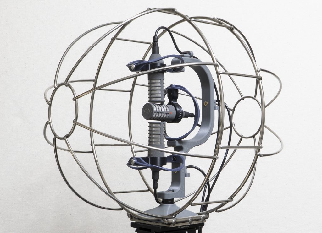
Coming at my own attempts for DMS with the side-address Schoeps CCM4V (and I am grateful to Schoeps for loan of the mics to test this) was, of course, from the perspective of using horizontal B-format either without any windshield (e.g. for location music recording, as with my bagpipe recordings last year) or within one of my Mega-Blimps. The latter, being much larger than windshields used with the commercially produced mounts, mean that a) the windshield basket can be oriented as designed and b) there is scope to reduce the proximity of structural supports around the mics. If the advantage of using side-address cardioids is that one can avoid the cluster of mics and consequence colouration arising from using end-address mics for the most demanding and critical applications, then it seems worth keeping the mics as free as possible of other sources of colouration, be that the windshield basket structure or the supports for the mics. Anyway, that is the rationale behind my DMS mount for the Mega-Blimp, albeit with a balance struck between transparency and isolation from structure-borne noise: i.e. the mics need shock-mounts (in this case mainly Radius Windshield hoops, but also using Rycote lyres where this reduces obstructions in front of the mics). The result does look similar to the horizontal B-format mount, although there are some significant tweaks to the geometry of the design to better fit the three Schoeps mics than the MKH 8000 mics.
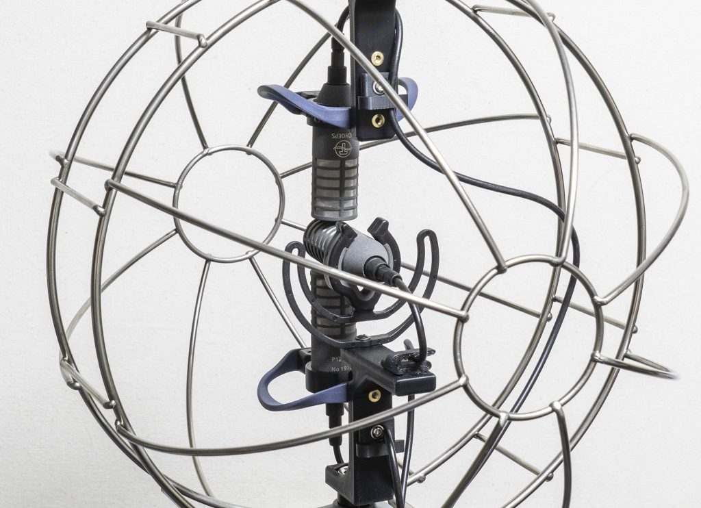
Mount for DMS with Schoeps CCM4V side-address cardioids and CCM8 fig 8 for indoor recording. The hoops and clips, plus the vertical arm to hold the top mic are the main residual items affecting the sound pickup, but the effects are limited to the rear-facing cardioid (the top mic).
Of course, such mounts that aim to minimize colouration are quite large, especially the revised version with its deeper rearward projection, but they fit happily in even my standard-sized Mega-Blimp, which, of course, minimizes additional colouration with its sparse and thin (mostly 3mm diameter) basket structure.
DMS mount (first version) in the shorter, standard, Mega-Blimp.
As with the horizontal B-format mic, such a rig presents challenges for the rear-facing upper mic, which here, as with the Schoeps/Rycote WSR DMS LU, has some on axis obstacles, in this case being the hoop and mic clip of the central mic, quite close to the cardioid, and beyond that the 18mm-wide vertical element of the mount. Looking at this more closely, it is, of course, possible to remove the hoop and mic clip by swapping to a Rycote lyre, which supports the fig 8 mic from underneath (and I have made provision in the mount for use of a rear lyre with a 9.5mm mount for the Lemo connector). And the impact of the 18mm-wide rear bar can be addressed by making this much thinner – in this case a slim 8mm (I tried 6mm, but that seemed too flimsy) – and also by moving this further still from the mic. There’s no such thing as a free lunch, however, with the downside of this version being less lateral stiffness for the arm to the upper mic (so not one to use if the mount is being subjected to much vibration). This revised version can be seen below.
Revised mount for DMS with Schoeps CCM4V side-address cardioids and CCM8 fig 8 for indoor recording, with the design modified to reduce the residual impact of structural elements on the rear-facing capsule. I could do with building in some cable clips to this design as with the previous version!And the same rig in a windshield.
For windshield use only, of course, it is possible to remove the need for an arm extending upwards to the top mic by adopting the approach previously used for one of my horizontal B-format rigs, which removes obstacles in front of the topmost (i.e. rear-facing cardioid) mic without the penalty of introducing more wobbliness to it.
The most transparent solution – well, that I can come up with! – for DMS in the Mega-Blimp, with separate mountings for the bottom and centre mics, and the top mic.A detail showing the largely unencumbered rear-facing (topmost) cardioid, which is a contrast to the situation in most DMS rigs.
So here we have it: an exploration of the three configurations used for DMS with SDC mics. Commercially available solutions exist for the first two options (with end-address cardioids), but are thin on the ground, to say the least, for the third option (with side-address cardioids). In all three cases there is significant scope for DIY solutions: indeed, for any particular mics this might well be essential. Hopefully some of my ramblings – or at least the photos – might inspire others to their own DMS solutions. Meanwhile, stay tuned for the practical comparisons in Part 2 and Part 3.
During my recent experiments to see whether you could fit an ORTF pair into the diminutive Mini-ALTO windshields from Radius Windshields, I began to wonder whether any of the four mics I found that worked for that purpose would allow other stereo configurations in the windshields, including XY. Of the mics I used for the ORTF experiment, the DPA 4011 capsule with the MMP-GS preamp was the only one short enough, having an overall length of 33mm; but the mic pair was on loan only and had a little too much self-noise for my liking (OK, 18dBA isn’t that bad!). You can imagine, then, that I was delighted to receive a pair of an upcoming smaller version of the Nevaton MC59 cardioid. The standard MC59S + 59/C sounds excellent and has low self-noise (8.6dBA), and is already a short mic at 47mm: rather incredibly, and largely due to the miniaturization of the preamp (just 5.5mm long), the MC59uS + 59/C2 combination halves that to give a length of just 23.5mm, and, with a side-exit cable, its effective length is less than half that of its sibling. I will be looking at the mics in more detail in different posts, but suffice it to say here that the idea with the MC59uS + 59/C2 has been to keep the same acoustic and electrical specs as the larger standard version.
Anyway, with such small mics in hand there was scope to have a play with the idea of XY in a Mini-ALTO. First up was the challenge of mounting the mics, and here I took advantage of the MC59uS having magnets in its base (goodness knows how they were squeezed in!), so I used some powerful Neodymium magnets (Simon Davies at Radius kindly sent me some of the ones they use in the windshields) and incorporated these into a mount: the rebated form of the magnets means it is really easy to keep them secure and not popping out.
3d-printed mount sans microphones, showing the magnet pairs (above the M3 brass insert fixings that fix these mounts to the overall XY mount). The mount has two halves, which are bolted together to form a 19mm diameter cylinder that is held by the Radius hoops. With the mics popped on the mounts: I do like the magnetic mounts – super slick!And some head-on views with and without one of the Mini-ALTO pods, along with a rear view.
So there you go: another fun test with a bit of 3d-modelling and printing for another type of stereo in a Mini-ALTO. As with my mid-side pairs, this fits comfortably in the smallest model – the Mini-ALTO 115. I’m very much aware that the MC59uS + 59/C2 mic is not yet in production (first batches are planned in October-November) and will be fairly expensive (more than the standard MC59/C models) and, therefore, won’t be a choice for every recordist. But, as I said in the Mini-ALTO ORTF post, if DIYers are wanting a much more affordable ultra-short cardioid, but still with decent specs and sound, then the Primo EM200 (which is what I believe is used in the well-respected Line Audio CM4) could easily be housed in an equally short, if not shorter, body: in fact, I’m rather puzzled that none of the many small businesses making Primo-capsuled mics haven’t done so already. Perhaps there are other mics that might fit. Whatever the case, I hope this small project might inspire others to have a play: the modularity of Radius hoops is a call to inventiveness!